Hong Kong Main
Board Listing
Stock Code: 2283
TK Precision Plastics (Shenzhen) Ltd. Chen Tianpeng
Introduction:
Weld lines are a common molding defect in the injection molding industry. Whether for precision plastic parts or large molds for automotive and household appliances, weld lines frequently pose challenges for injection molding manufacturers. As weld lines are a subjective cosmetic defect, it is difficult for software to directly represent them. As a result, Moldflow analysis does not provide a clear, visual result to display or predict this molding defect. This paper, through case studies, demonstrates how modifying product structure and combining Moldflow software can effectively address this issue.
Case Study (1 example)
> 1. Case Introduction
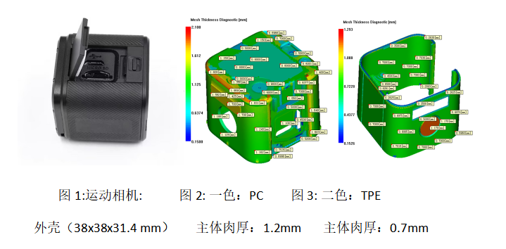
The outer shell of the action camera measures 38x38x31.4 mm (Figure 1). The primary material is PC, with a wall thickness of 1.2 mm (Figure 2). The secondary material is TPE, with a wall thickness of 0.7 mm (Figure 3).
2. Original Design Plan
The original design for the product is shown in Figure 4.

Figure 4: Original design plan
3. Current Issues
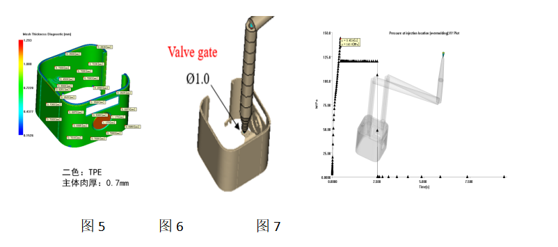
Issue 1: Due to the thin wall thickness of the secondary material, and the relatively poor flow characteristics of the TPE, a higher injection speed is required to completely fill the mold (Figures 5-7).
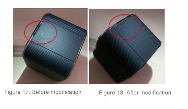
Issue 2: There are appearance issues, such as weld lines, caused by the thin walls, high injection speed, and the gate being located near the outer sidewall. In this case, due to the thin-walled design, the injection pressure is already very high, making it impossible to move the gate away from the outer sidewall area. However, the client does not approve any changes to the overall wall thickness, agreeing only to modify the wall thickness locally in the top region. During the machine adjustment process, we found that using low speed couldn’t completely fill the product, and at high speed, the weld lines couldn’t be perfectly adjusted (Figure 8).
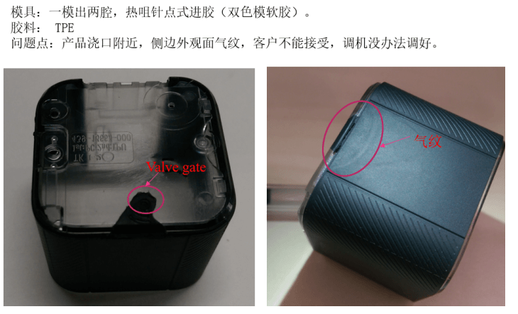
Figure 8
4. Root Cause Analysis and Improvement Plan
There are many potential causes for weld lines, including excessive fill speed, high temperatures, and trapped air. Based on the Moldflow filling analysis for this case, the proximity of the weld line to the gate suggests that the primary causes of the weld lines could be fast injection speed and high shear temperature (Figure 9).
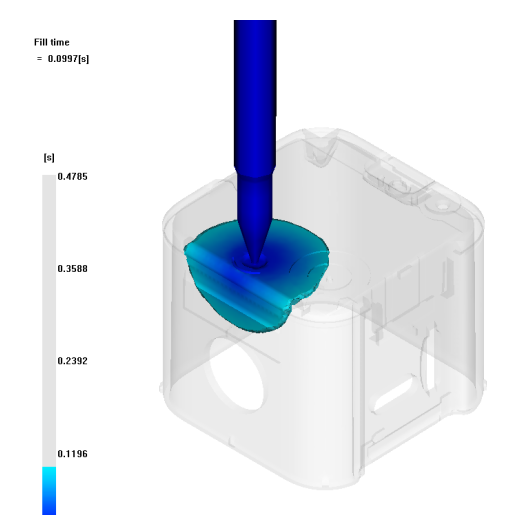
Figure 9
Possible Causes of Weld Lines: from a structural perspective (Figure 10), the location of the weld line has an angled section that is close to the gate, with uneven wall thickness. When the melt flows through this area, the speed increases, and shear heat rises sharply, causing gas to form. As the material is guided by the angle, it flows toward the mold surface along the direction of the red arrows (Figure 11), which can lead to rollover and result in weld lines. Therefore, the configuration of this section is likely a significant factor contributing to the formation of the weld lines.

Figure 10: 3D cross-section of the product showing the location of the weld line
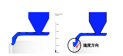
Figure 11: Possible causes of weld lines
As shown in Figure 12, the presence of the angle and its proximity to the gate causes the melt to move quickly and, due to inertia, strike the mold sidewall at an angle along the arrow direction, leading to the formation of weld lines.
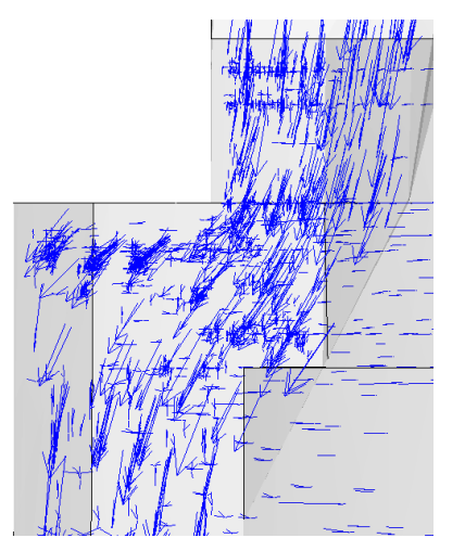
Figure 12: Speed Direction Before Modification
To eliminate weld lines and reduce shear heat, the melt flow direction was adjusted to avoid the material striking the mold surface at an angle. This modification involved adjusting the angle, ensuring more uniform wall thickness, and adding a wave section to the gate location to further improve the wall thickness uniformity.
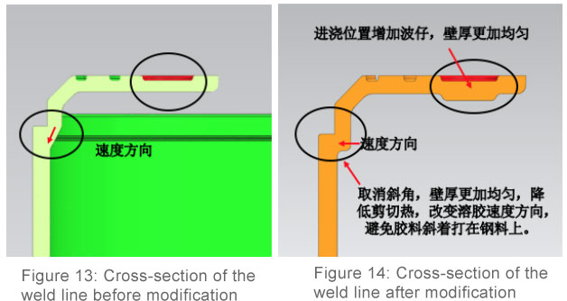
As shown in Figures 15 and 16, after removing the angled section, the melt flow direction became more consistent. The material now generates centripetal force at the radius (R), and under the influence of this force, it adheres to the surface of the primary material, filling more evenly. This change reduces the possibility of shear and rollover, thereby improving the surface quality of the product.
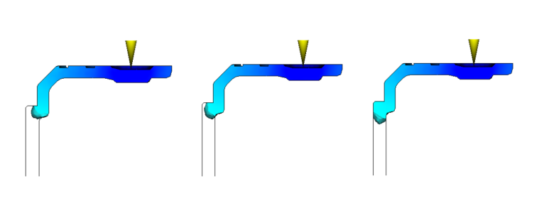
Figure 15: Moldflow analysis after modification
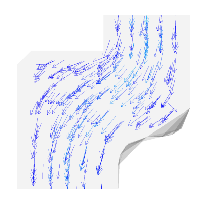
Figure 16: Magnified view of the localized area
Comparison of Actual Product Improvement (Figures 17-18)
4. Project Summary
Weld lines near the gate are commonly found in thin-walled products subjected to high pressure. The primary causes of weld lines include high shear rate, poor venting, and structural issues. The success of this case demonstrates the importance of addressing surface issues early in the design phase to minimize molding defects caused by structural factors. This has been a significant learning experience for us. In the past, similar product improvements were costly (around RMB 200,000) and time-consuming (approximately 3 months). By using Moldflow to analyze the gate position and size before mold production, we were able to optimize the structure more effectively. This approach significantly reduced the improvement costs to RMB 50,000 (including quality adjustments) and shortened the improvement time to just 10 days. Moreover, it led to a notable improvement in product quality.
Moldflow Long-term Application Benefits Analysis for the Company
1. Project Costs
By using Moldflow, the project cycle can be shortened by 1 to 3 months. Each project saves an average of RMB 100,000, with approximately 20 projects per year. Total Project Cost Savings: RMB 100,000 × 20 = RMB 2,000,000
2. Mold Costs
With Moldflow, the number of trial moldings can be reduced by 1 to 2 cycles. Each mold saves ¥10,000, and with an average of 50 molds analyzed annually. Total Mold Cost Savings: RMB 10,000 × 50 = RMB 500,000
Total Savings: RMB 2,000,000 + RMB 500,000 = RMB 2,500,000 per year
Experience Sharing
1. Experience Sharing #1: Accurate Analysis of Fill Status
To accurately analyze the filling process using Moldflow, there are three key points to consider: 1. A correct mesh model, with an appropriate number of mesh elements—too few can affect the analysis accuracy. 2. Correct material parameters—ensure that material information is precise and accurate. 3. Reference to actual process parameters is necessary for realistic results.
2. Experience Sharing #2: How to Set Proper Injection Time
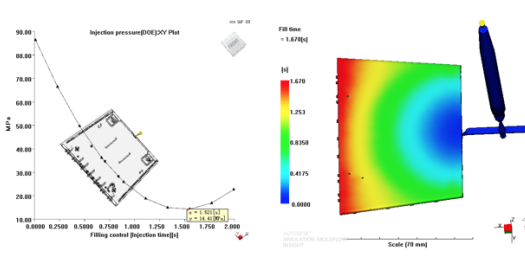
Using Moldflow’s Design of Experiments (DOE) functionality: 1. It helps identify the minimum injection pressure required for optimal injection time. 2. You can also set the mold temperature range to determine the most suitable filling speed.
Outlook for the Future
The injection molding industry is increasingly reliant on Moldflow. It is not only recognized by clients but also meets the needs of companies. With the growing intensity of competition and higher quality demands, we must leverage Moldflow in the most effective way to create value for the company. Going forward, Moldflow will continue to advance toward higher quality standards. It will focus on summarizing and addressing various injection molding defects, including prediction, evaluation, and solutions. For injection molding issues that cannot yet be directly reflected in the analysis results, we hope that Moldflow will progressively improve and become even better.
